Part Number Master
Overview
The Part Number Master application is a foundational component of Maximo for Aviation that provides comprehensive management of part numbers, including Configuration-Managed (CM) part numbers. This application serves as the central repository for all part number definitions that are essential for aircraft configuration management, maintenance planning, and inventory control. The application is a modified version of the core Manage Item Master application with additional fields, tabs and related attributes to manage configuration-managed part numbers. Configuration-Managed Part Numbers represent the components that make up an aircraft or complex asset.
CM Part Numbers are used in Models and form part of the engineering reference data used to define an as-designed configuration. They establish the baseline for what components should be installed on an aircraft and provide the framework for tracking actual vs. designed configurations.
The Part Number Master is tightly integrated with the Model application, Master Task Cards, Operators Maintenance Program (OMP) and the Build Data Interpreter (BDI) to ensure configuration compliance and automated maintenance program management.
Key Capabilities:
- Define and manage part numbers with comprehensive attributes
- Establish configuration-managed part numbers for aircraft components
- Define serial number formats and ranges for traceability
- Create serial range usable-on codes (UOCs) for effectivity management
- Display Master Task Cards for CM Parts (used for automated Task Card generation)
- Support interchangeable parts and alternates
- Manage part specifications, vendors, and storeroom locations
- Track part assembly structures and relationships
- Define ATA chapter codes for system organization
- Support both hardware and software part number management
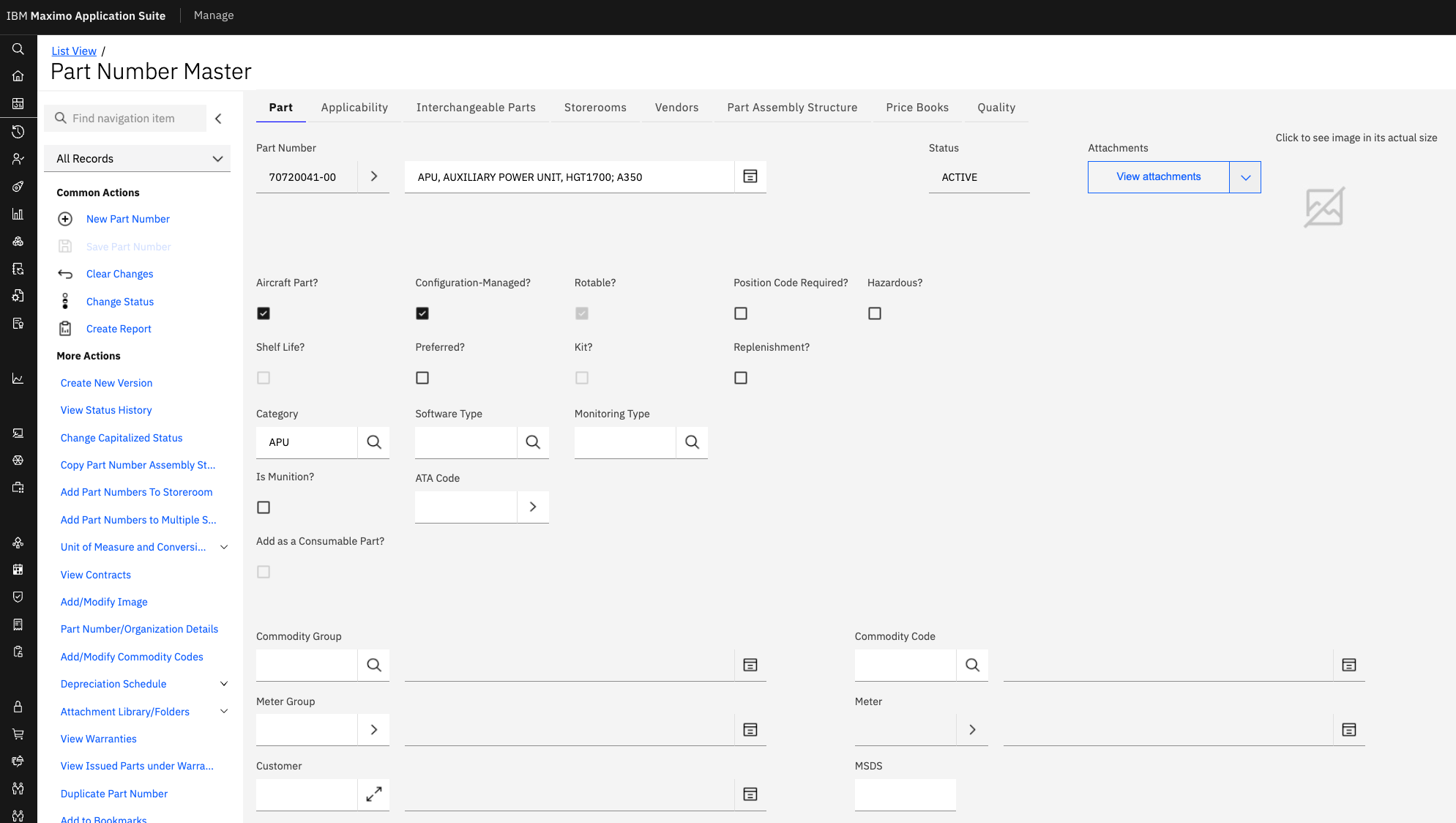
Field Information
The Part Number Master application contains numerous fields that define the characteristics, attributes, and relationships of each part number. Understanding these fields is essential for consultants implementing the system and ensuring data quality.
Core Identification Fields
| Field Name | Description | Example Value | Required |
|---|---|---|---|
| Part Number | The unique identifier of the Part | APU-7766 | Yes |
| Part Set | The Part Set to which the Part Belongs | AVINPNSET | Yes |
| Description | A detailed description of the part | Auxillary Power Unit | Yes |
The Part Number in combination with the Part Set field forms its unique identifier in the system and once saved, it cannot be changed. Plan your part numbering scheme carefully before implementation.
Classification and Categorization
| Field Name | Description | Example Value | Notes |
|---|---|---|---|
| Category | The type of part (HARDWARE, SOFTWARE, etc.) | HARDWARE | Used to classify parts by type |
| Software Type | The type of software if categorized as SOFTWARE | FLS (Field Loadable Software) | Only applicable for software parts |
| ATA Code | Air Transport Association chapter code | 49-00 (APU) | Organizes parts by aircraft system |
| Commodity Group | High-level commodity classification | AVIONICS | For procurement and inventory grouping |
| Commodity Code | Detailed commodity classification | NAVIGATION_EQUIPMENT | More specific than commodity group |
Common Part Categories:
- HARDWARE - Physical components and assemblies
- SOFTWARE - Software loads, firmware, and applications
- ENGINE - Aicraft Engine
- APU - Auxilliary Power Unit
Configuration Management Fields
| Field Name | Description | Example Value | Impact |
|---|---|---|---|
| Configuration-Managed? | Indicates if this is a CM part number | ☑ (checked) | Enables use in Models and BDI validation |
| Aircraft Part? | Indicates if this part is used on aircraft | ☑ (checked) | Determines if part appears in aircraft BOMs |
| Rotable? | Indicates if part is repairable/rotable | ☑ (checked) | Affects inventory and maintenance processes |
| Serial Format | Format of serial numbers for this part | AANNN | Defines expected serial number pattern |
| Position Code Required? | Whether position code is mandatory | ☐ (unchecked) | Controls position tracking requirements |
| Hazardous? | Indicates if part contains hazardous materials | ☐ (unchecked) | Triggers special handling requirements |
Configuration-Managed parts are the foundation of the Model application. Only CM parts can be used to define aircraft build hierarchies and configuration rules.
Serial Format Patterns:
- A - Alphabetic character
- N - Numeric digit
- X - Alphanumeric character (letter or number)
- AANNN - Two letters followed by three numbers (e.g., AB123)
- NNNNN - Five numeric digits (e.g., 12345)
- AANNNN - Two letters followed by four numbers (e.g., XY1234)
Inventory and Procurement Fields
| Field Name | Description | Example Value | Purpose |
|---|---|---|---|
| Shelf Life? | Indicates if part has a shelf life | ☐ (unchecked) | Triggers expiration tracking |
| Preferred? | Indicates if this is a preferred part | ☐ (unchecked) | Guides procurement decisions |
| Kit? | Indicates if part is a kit of components | ☐ (unchecked) | Affects issue and inventory processes |
| Replenishment? | Indicates if part should be auto-replenished | ☐ (unchecked) | Triggers automatic reorder |
| Add as Consumable Part? | Add to consumable parts list | ☐ (unchecked) | Makes part available for consumption |
Monitoring and Tracking
| Field Name | Description | Example Value | Usage |
|---|---|---|---|
| Monitoring Type | Type of condition monitoring applied | HT (Hard Time) | Defines monitoring approach |
| Meter Group | Group of meters associated with part | ENGINE_METERS | Links to meter definitions |
| Meter | Specific meter for tracking usage | FLIGHT_HOURS | Primary usage meter |
| MSDS | Material Safety Data Sheet reference | MSDS-12345 | Safety information reference |
Monitoring Type Examples:
- CM - Condition Monitoring
- HT - Hard Time
- LLP - Life Limited Part
- OC - On Condition
- ST - Soft Time
Serial Ranges for Part Number
The Serial Ranges functionality allows for the definition of one or more Serial Range Usable on Codes (UOC) for each configuration-managed part number. Serial Range UOCs are a powerful feature that enables precise control over which serial numbers of a part are applicable to specific aircraft or configurations.
Purpose of Serial Range UOCs:
- Define effectivity for specific serial number ranges
- Support engineering changes that affect only certain serial numbers
- Enable configuration rules based on component serial numbers
- Track which part serial numbers are valid for specific aircraft
The Serial Range UOC is a unique value within the context of the CM Part Number that is used to identify a range of serial numbers. These UOCs are then referenced within specific configuration rules in the Model application to specify which positions or part numbers are valid for specific ranges of end item serial numbers.
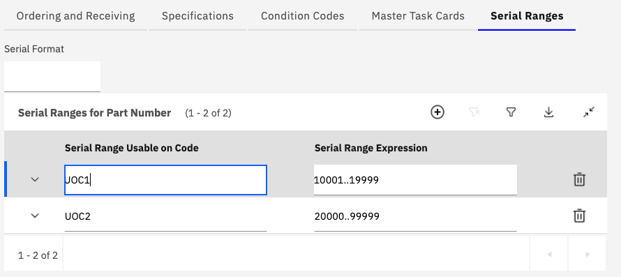
Serial Range UOC Structure
Each Serial Range UOC consists of two key components:
| Component | Description | Example |
|---|---|---|
| Serial Range Usable on Code | Unique identifier for the serial range | UOC1, UOC2, EARLY_BUILD, LATE_BUILD |
| Serial Range Expression | Defines the actual serial numbers included | 10001..19999, 20000..99999 |
Serial Range Expression Formats:
The Serial Range Expression can be defined using three different formats:
-
Comma-Separated List of Serial Numbers
- Format: Individual serial numbers separated by commas
- Example:
AA001, AA004, AA009 - Use Case: When only specific, non-consecutive serial numbers are affected
- Result: Only the explicitly listed serial numbers are included
-
Range Notation Using Double Dots
- Format: Start serial number, double dots (..), end serial number
- Example:
A001..A100 - Use Case: When a continuous range of serial numbers is affected
- Result: Includes A001, A002, A003, ... all the way to A100 inclusive
- Note: The system automatically includes all serial numbers between start and end
-
Combination of Both Formats
- Format: Mix of individual serial numbers and ranges
- Example:
A001, A003, A006..A009 - Use Case: When you need both specific serial numbers and ranges
- Result: Includes A001, A003, A006, A007, A008, A009
- Note: Provides maximum flexibility for complex effectivity scenarios
Serial Range Expression Examples:
| Scenario | UOC Code | Serial Range Expression | Interpretation |
|---|---|---|---|
| Early production units | EARLY_PROD | 10001..19999 | All serial numbers from 10001 through 19999 |
| Late production units | LATE_PROD | 20000..99999 | All serial numbers from 20000 through 99999 |
| Specific test units | TEST_UNITS | T001, T002, T005, T010 | Only these four test serial numbers |
| Mixed effectivity | MIXED_EFF | 1001..1050, 1075, 1100..1150 | Range 1001-1050, plus 1075, plus range 1100-1150 |
| Pre-modification | PRE_MOD | 5001..5500, 5550..5600 | Two separate ranges before modification |
| Post-modification | POST_MOD | 5601..9999 | All units after modification cutoff |
Creating Serial Range UOCs
Step-by-Step Process:
- Navigate to the Serial Ranges tab in the Part Number Master
- Click Add Row to create a new serial range UOC
- Enter a unique Serial Range Usable on Code (e.g., UOC1, EARLY_BUILD)
- Define the Serial Range Expression using one of the three formats
- Validate the expression syntax
- Save the serial range UOC
Serial Range UOC codes must be unique within the context of a single part number. However, the same UOC code can be used across different part numbers with different serial range expressions.
Master Task Cards for Part Number
The Master Task Cards for Part Number section displays all Master Task Cards that are related to the current configuration-managed part number. This relationship is fundamental to Maximo for Aviation's automated preventive maintenance generation capability and ensures that the correct maintenance tasks are created for each installed component.
Relationship Overview:
- Master Task Cards are linked to part numbers in the Master Task Card application
- The relationship is typically established when creating or editing Master Task Cards
- Multiple Master Task Cards can be associated with a single part number
- Each task card defines specific maintenance requirements for the component
- The relationship drives automated PM generation through BDI validation
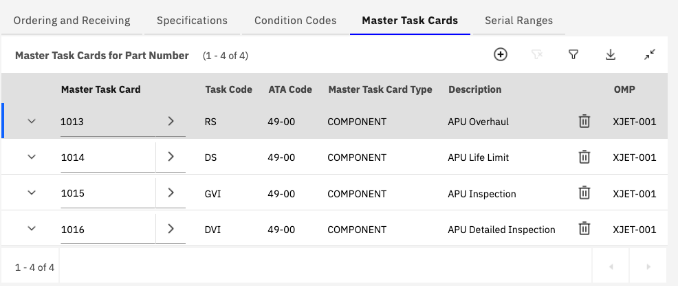
Master Task Card Information Display
The Master Task Cards table shows key information about each related task card:
| Column | Description | Example Value |
|---|---|---|
| Master Task Card | Unique identifier for the task card | 1013, 1014, 1015, 1016 |
| Task Code | Short code identifying the task type | RS, DS, GVI, DVI |
| ATA Code | ATA chapter code for the task | 49-00 (APU) |
| Master Task Card Type | Category of maintenance task | COMPONENT, AIRCRAFT, SYSTEM |
| Description | Brief description of the task | APU Overhaul, APU Life Limit, APU Inspection |
| OMP | Operators Maintenance Program reference | XJET-001 |
Additional Tabs and Functionality
The Part Number Master application includes several additional tabs that provide extended functionality for managing part numbers, their relationships, and associated data.
Applicability Tab
Defines where and how the part number can be used:
- Aircraft models and variants
- System applicability
- Configuration restrictions
- Interchangeability rules
Interchangeable Parts Tab
Manages alternate and interchangeable part numbers:
- Define substitute part numbers
- Specify interchangeability conditions